How Does A Mass Flow Controller Work?
794
0
·
2021/01/18
·
2 mins read
☕
WriterShelf™ is a unique multiple pen name blogging and forum platform. Protect relationships and your privacy. Take your writing in new directions. ** Join WriterShelf**
WriterShelf™ is an open writing platform. The views, information and opinions in this article are those of the author.
Article info
Categories:
⟩
⟩
Tags:
Date:
Published: 2021/01/18 - Updated: 2021/01/19
Total: 423 words
Like
or Dislike
More from this author
More to explore


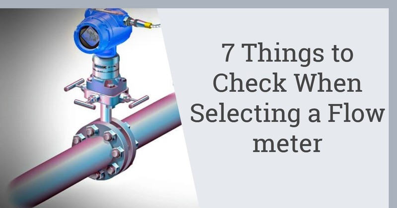
A mass flow controller is a tool to gauge and control the flow of liquids and gases in the system. A mass controller is a favored option for most measurements as it is not altered by stress and fluid state.
This strength gives it a favor in industries for accurate readings despite fluid state changes. But how exactly does a mass flow controller work?
Kinds of Flow Controllers
Controllers are classified according to how they are calibrated and reused. There are two main types of digital and analog. An analog flow controller is calibrated once to work with a special fluid.
Digital flow controllers, on the other hand, are versatile and can work as a liquid flow controller.
How it works
The device is divided into two parts, the CPU and the measurement portion. The flow part consists of a bypass, a special circuitry, a sensor, and a control valve. The CPU part of the circuit gives high efficiency and versatility.
A fluid is let into the system through an inlet joint where it flows between the bypass and the flow rate sensor. The role of the sensor is to record the mass flow rate of the fluid. As it provides the measurements, the control valve alters the flow depending on the noted signal. There is a valve to ensure that the measured flow rate and the incoming flow rate are equal.
The circuit works to control the stress and heat of the fluid to enhance accuracy.
Steps
Conclusion
A mass & liquid flow controller is versatile and used in the control of many fluids. For better use and durability, you need to know the laws and the device's inner workings. A fair reading of this article gives an upper hand in handling the device and gaining efficiency.